Le tadalafil possède une affinité marquée pour la PDE5, mais épargne en grande partie les isoformes PDE1, PDE2 et PDE11, réduisant ainsi le risque d’effets extra-caverneux. L’action se traduit par une augmentation contrôlée de la circulation sanguine locale, indépendante des variations alimentaires. Sa pharmacocinétique repose sur une absorption digestive rapide, un métabolisme hépatique par CYP3A4 et une distribution tissulaire large. La biodisponibilité reste stable, et l’équilibre plasmatique est atteint en quelques jours lors d’administrations répétées. Les interactions cliniquement significatives surviennent avec les inhibiteurs puissants de CYP3A4 tels que le kétoconazole. Dans la littérature pharmacologique, acheter cialis 20 mg est souvent associé à des schémas d’utilisation basés sur la durée prolongée de son action.
Es50-22b
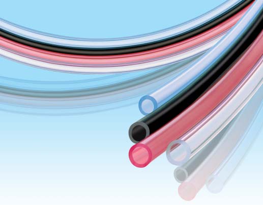
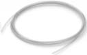
FEP Tubing (Fluoropolymer) Inch size (Series TIH) is introduced. Heat resistance:200°C Series TH/ TIH It changes according to the operating pressure. Applications Refer to the graph of the max. operating pressures on page 1, 2. General pneumatic piping Color variations Semiconductor Medical care Automobile Translucent Certified to current Food Sanitation Size variations Legislation Metric size: ø4 to ø12 Ministry of Japanese Health and Inch size: 1/8" to 3/4" (ø3.18 to ø19.05) Safety, directive #370,1959 FEP Tubing (Fluoropolymer) Metric Size Series TH TH0402 TH0425 TH0604 TH0806 TH1075 TH1008 TH1209 TH1210 Tubing O.D. (mm) Tubing I.D. (mm) Translucent Red (Translucent) Blue (Translucent) BU Black (Opaque) Specifications How to measure the minimum bending radius.
One-touch fittings: Series KQ, KJ Insert fittings: Series KF
Applicable fittings
Miniature fittings: Series M, MS (Hose nipple type)
Max. operating 100°C pressure (MPa) 200°C 0.4
Refer to below “Max. Operating Pressure.”
Min. bending radius (mm) Operating temperature
Air, Inert gas: -20 to 200°C Water: 0 to 100°C (No freezing)
the other end closer. Measure 2R at the point where the
Material
FEP (Fluorinated Ethylene Propylene Resin)
outside diameter's rate of change is 5%.
Note 1) When using a fluid in liquid form, the surge pressure must not exceed the maximum operating pressure. A surge
pressure higher than the maximum operating pressure can cause breakage of the fittings, or rupture of the tubing.
Furthermore, an abnormal temperature increase due to adiabatic compression can also result in ruptured tubing. Max. Operating Pressure
Note 2) Do not use in locations where the FEP tubing will move.
Be sure to operate under the maximum operating pressure conditions using the lower maximum operating
specification of either the tubing or fittings.
After long term use or under high temperatures, some fittings leakage may occur due to material deterioration with
age. Perform periodic inspections, and if any leakage is detected, replace with a new product immediately.
(Refer to maintenance part of "Tubing Precautions" on the Back page 2.)Refer to Best Pneumatics catlog Vol. 15 for all other precautions.
For High Purity Fluoropolymer, refer to the precautions of CAT.ES70-17, "High Purity Fluoropolymer Fittings &
Note 3) Minimum bending radius is measured as shown left as representative values.
Allow extra length when piping since the tubing may crush if bent more than the min. bending radius.
TH0806/TH1075/TH1209 How to Order Metric size TH1008/TH1210 Indication of tubing model Length per roll Color indication 100 Note)
Note) The maximum operating pressure varies dependant
on the I.D. bore size even if the O.D. is the same. FEP Tubing (Fluoropolymer) Inch Size Series TIH TIHA01 TIHB01 TIHC01 TIHA05 TIHB05 TIHA07 TIHB07 TIHA11 TIHB11 TIH13 Tubing O.D. mm
0.093" 0.086" 0.065" 0.137"
Tubing I.D.
2.36 2.18 1.65 3.48 3.15 4.57 3.95 6.99 6.33
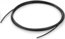
Translucent Red (Translucent) Blue (Translucent) BU Black (Opaque) Specifications How to measure the minimum bending radius. Applicable fittings
One-touch fittings: Series KQ, KJ Fluoropolymer fittings: Series LQ
Max. operating pressure (MPa) 200°C
Refer to below “Max. Operating Pressure.”
Min. bending radius (mm) Operating temperature
Air, Inert gas: -20 to 200°C Water: 0 to 100°C (No freezing)
the tubing into a U shape. Fix one end and gradually move
Material
FEP (Fluorinated Ethylene Propylene Resin)
the other end closer. Measure 2R at the point where the
Note 1) When using a fluid in liquid form, the surge pressure must not exceed the maximum operating pressure. A surge
pressure higher than the maximum operating pressure can cause breakage of the fittings, or rupture of the tubing.
Furthermore, an abnormal temperature increase due to adiabatic compression can also result in ruptured tubing.
Note 2) Do not use in locations where the FEP tubing will move.
Be sure to operate under the maximum operating pressure conditions using the lower maximum operating
Max. Operating Pressure
specification of either the tubing or fittings.
After long term use or under high temperatures, some fittings leakage may occur due to material deterioration with
age. Perform periodic inspections, and if any leakage is detected, replace with a new product immediately.
(Refer to maintenance part of "Tubing Precautions" on the Back page 2.)Refer to Best Pneumatics catlog Vol. 15 for all other precautions. For High Purity Fluoropolymer, refer to the precautions of CAT.ES70-17, "High Purity Fluoropolymer Fittings &
Note 3) Minimum bending radius is measured as shown left as representative values.
Allow extra length when piping since the tubing may crush if bent more than the min. bending radius.
TIHB05/TIHB11 TIHA01/TIHB01/TIHA05 How to Order TIHA07/TIHA11/TIH13 Inch size Indication of tubing model Length per roll Color indication
Note) 100ft (33m) roll is available with
Note) The maximum operating pressure varies dependant
on the I.D. bore size even if the O.D. is the same. Chemical Resistance of the Fluoropolymer FEP Material Chemicals in this table are inactive against FEP material Note 1), however physical properties may be effected by temperature or pressure change. Please make sure that operating conditions do not cause problems since the use of FEP tubing under chemical environment is unsecured.
Note 1) “Inactive in chemistry terminology” means - not to cause any chemical reaction. Reference cited: Teflon®, the fluoropolymer handbook, Manual for the chemical applications of Teflon®. Du Pond-Mitsui Fluorochemicals Co., Ltd.
Teflon® is a registered trademark for the fluoropolymer produced by E.I du Pond de Nemours & Company (Inc.) and Du Pond-Mitsui Fluorochemicals Co., Ltd. Series TH/TIH Safety Instructions
These safety instructions are intended to prevent a hazardous situation and/or equipment damage. These instructions indicate the level of potential hazard by a label of "Caution", "Warning" or "Danger". To ensure safety, be sure to observe ISO 4414 Note 1), JIS B 8370 Note 2) and other safety practices. Caution : Operator error could result in injury or equipment damage. Warning : Operator error could result in serious injury or loss of life. Danger : In extreme conditions, there is a possible result of serious injury or loss of life.
Note 1) ISO 4414: Pneumatic fluid power -- General rules relating to systems
Note 2) JIS B 8370: Pneumatic system axiom
1. The compatibility of pneumatic equipment is the responsibility of the person who designs the pneumatic system or decides its specifications. Since the products specified here are used in various operating conditions, their compatibility with the
specific pneumatic system must be based on specifications or after analysis and/or tests to meet your
specific requirements. The expected performance and safety assurance will be the responsibility of the
person who has determined the compatibility of the system. This person should continuously review the
suitability of all items specified, referring to the latest catalog information with a view to giving due
consideration to any possibility of equipment failure when configuring a system. 2. Only trained personnel should operate pneumatically operated machinery and equipment. Compressed air can be dangerous if handled incorrectly. Assembly, handling or maintenance of
pneumatic systems should be performed by trained and experienced operators. 3. Do not service machinery/equipment or attempt to remove components until safety is confirmed. 1. Inspection and maintenance of machinery/equipment should only be performed once measures to
prevent falling or runaway of the driven object have been confirmed.
2. When equipment is to be removed, confirm the safety process as mentioned above. Cut the supply
pressure for this equipment and exhaust all residual compressed air in the system.
3. Before machinery/equipment is restarted, take measures to prevent shooting-out of cylinder piston
4. Contact SMC if the product is to be used in any of the following conditions:
1. Conditions and environments beyond the given specifications, or if product is used outdoors.
2. Installation on equipment in conjunction with atomic energy, railway, air navigation, vehicles, medical
equipment, food and beverages, recreation equipment, emergency stop circuits, clutch and brake
circuit in press applications, or safety equipment.
3. An application which has the possibility of having negative effects on people, property, or animals,
Series TH/TIH Tubing Precautions Be sure to read before handling. Refer to back page 1 for safety instructions. Selection Air Supply 1. Confirm the specifications. 1. Types of fluid
The products appearing in this catalog are designed for use only in
This product is designed for use with compressed air. Consult with
compressed air systems (including vacuum).
SMC if a different fluid is to be used.
Do not use outside the specified ranges of pressure, temperature,
Consult with SMC regarding products for use with general purpose
etc., as this may cause damage or malfunction. (Refer to
fluids, to confirm which fluids can be used. 2. When there is a large amount of drainage.
SMC cannot assure the product quality when fluids other than air,
Compressed air containing a large amount of drainage can cause
the malfunction of pneumatic equipment. An air dryer or Drain
Catch should be installed upstream from filters. 2. In case of using the product for medical care 3. Drain management
This product is designed for use with compressed air system
If air filter drains are not flushed regularly, the drainage will flow
applications for medical care purposes. Do not use in contact with
downstream leading to the malfunction of pneumatic equipment.
human bodily fluids, body tissues or transfer applications to a
In cases where the management of drain flushing will be difficult,
the use of filters with automatic drains is recommended.
For details on the quality of compressed air mentioned above, refer
to SMC's "Best Pneumatics" catalog vol. 14.
1. Do not use in locations where the connecting threads and tubing
connection will slide or rotate. The connecting theads and tubing connection will come apart under these conditions.
Use rotary type one-touch fittings (Series KS, KX) in cases where sliding or rotation will occur. Only air can be used as the operating
Operating Environment
fluid, when using rotary type one-touch fittings.
2. Use tubing at or above the minimum bending radius. Using below
the minimum bending radius can cause breakage or flattening of the tubing.
1. Do not operate in locations in an explosive atmosphere.
3. Never use the tubing for anything flammable, explosive or toxic
2. Do not operate in locations where vibration or impact occurs.
such as, gas, fuel gas, or cooling mediums, since the contents can
3. In locations near heat resources, block off radiant heat. Maintenance Mounting
1. Check for the following during regular maintenance, and replace
1. Before mounting confirm the model and size, etc. Also, confirm that
there are no blemishes, nicks or cracks in the product.
a) Scratches, gouges, abrasion, corrosion
2. When tubing is connected, consider factors such as changes in the
tubing length due to pressure, and allow sufficient leeway.
c) Twisting, flattening or distortion of tubing
3. Mount so that fittings and tubing are not subjected to twisting,
d) Hardening, deterioration or softness of tubing
pulling or moment loads. This can cause damage to fittings and flattening, bursting or disconnection of tubing, etc.
2. Do not repair or patch the replaced tubing or fittings for reuse.
4. Mount so that tubing is not damaged due to tangling and abrasion.
3. When using insert or miniature fittings over a long period, some
This can cause flattening, bursting or disconnection of tubing, etc.
leakage may occur due to age deterioration of the materials. Perform periodic inspections, and if any leakage is detected, correct the problem by additional tightening. If tightening becomes
ineffective, replace the fittings with a new product immediately. 1. Preparation before piping
Before piping is connected, it should be thoroughly blown out with air (flushing) or washed to remove chips, cutting oil and other debris from inside the pipe. Not allowing chips of the piping thread or the seal material to go in. SMC'S GLOBAL MANUFACTURING, DISTRIBUTION AND SERVICE NETWORK SLOVAKIA
SMC Priemyselná Automatizáciá, s.r.o. AUSTRIA SMC Pneumatik GmbH SLOVENIA THAILAND SPAIN/PORTUGAL NORTH AMERICA SWITZERLAND
SMC Corporation (Mexico) S.A. de C.V. GERMANY SMC Pneumatik GmbH SOUTH AMERICA ARGENTINA HONG KONG INDONESIA NETHERLANDS MALAYSIA VENEZUELA PHILIPPINES SINGAPORE AUSTRALIA
SMC Industrial Automation Polska Sp.z.o.o.
SMC Pneumatics (Australia) Pty. Ltd. SOUTH KOREA NEW ZEALAND RUSSIA SMC Pneumatik LLC.
1-16-4 Shimbashi, Minato-ku, Tokyo 105-8659 JAPANTel: 03-3502-2740 Fax: 03-3508-2480URL http://www.smcworld.com 2004 SMC Corporation All Rights Reserved
Specifications are subject to change without prior notice
1st printing HV printing IW 120KS Printed in Japan.
and any obligation on the part of the manufacturer.
This catalog is printed on recycled paper with concern for the global environment.
LA SCHIZOPHRÉNIE Dr Pierre Lalonde, psychiatre La schizophrénie est une maladie du cerveau qui se manifeste par des perturbations de certaines fonctions mentales. Ce n'est pas une maladie de l'âme, ni un manque de volonté, ni une double personnalité, mais bien un " défaut " de certains circuits neuronaux du cerveau. Il en découle une invalidité, un handicap et, malheureusement
CASE STUDY Project: Geotechnical Engineer: Structural Engineer: Contractor: Pinnacle Job Description: Renovation of this existing commercial space from a retail outlet to a Laser Eye Clinic, necessitated formation of a larger mezzanine floor supported on pilings, through an existing main floor structural slab, as the remainder of the building is pile suppor
 FEP Tubing (Fluoropolymer)

 FEP Tubing (Fluoropolymer)
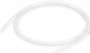

 FEP Tubing (Fluoropolymer)